
 EN
EN
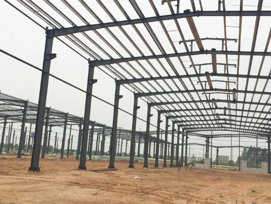
Clear-Span Design for Uninterrupted Equipment Layout and Workflow
Why Internal Columns Restrict Heavy Machinery Placement and Material Flow
Internal columns fragment floor space, turning production floors into navigational challenges for forklifts and automated guided vehicles (AGVs). Each column occupies usable square footage—and more critically, creates a functional exclusion zone that extends well beyond its physical footprint. Forklifts require 12–14 feet of turning radius, and columns erode aisle width or force machinery into suboptimal positions. Blind corners increase collision risk and slow material flow; operators must repeatedly stop to verify sightlines, reducing picking and staging efficiency. In conventional buildings, equipment placement is often dictated by column spacing—not operational logic—leading to bottlenecks, wasted travel, and inflexible layouts. Once installed, reconfiguring around columns becomes costly and disruptive. Clear-span industrial metal buildings eliminate this constraint, delivering a fully open, column-free floor plate where every square foot supports production, and workflows are optimized solely for manufacturing needs—not structural compromise.
Engineering Clear-Span Industrial Metal Buildings Up to 150+ Feet Wide
Achieving column-free spans of 150 feet and beyond relies on rigid-frame engineering that transfers roof and crane loads directly to perimeter columns without interior supports. Tapered steel columns and welded plate-girder frames deliver the required stiffness, while high-strength Q355B steel enables shallower roof pitches and lighter framing—without sacrificing load capacity. Precision-engineered purlins and girts provide lateral stability, and computer-modeled moment connections ensure integrity under dynamic suspended crane loads. These spans remove obstacles to overhead crane rail alignment and accommodate tall, wide-footprint equipment—from large CNC lines and paint booths to robotic assembly cells. The result is a fully reconfigurable floor plate: as production evolves, the building remains adaptable, offering long-term flexibility with a single, strategic structural investment.
Optimized Eave Height and Vertical Clearance for Overhead Cranes and Tall Machinery
Minimum Functional Clear Heights by Equipment Type (CNC, Assembly Lines, Paint Booths)
Eave height must be determined by the tallest piece of equipment—not generic benchmarks. CNC machining centers with automatic tool changers typically require 18–22 feet of clear vertical space for safe loading, maintenance access, and tool changer operation. Assembly lines using overhead power-and-free conveyors often need 24–28 feet to sustain continuous material flow and maintain worker walkways beneath. Spray booths with elevated hanger systems and air plenums commonly demand 22–26 feet; high-bay finishing lines may push requirements to 30 feet. Overhead cranes add a critical variable: eave height must accommodate full hook travel plus the lifted load’s maximum height—typically requiring an additional 4–6 feet above the crane rail elevation. Defining these functional minimums early prevents structural rework and ensures the enclosure fully supports all process equipment from day one.
Coordinating Crane Runways, Mezzanines, and HVAC Ductwork Within Vertical Envelope
The vertical envelope is a finite resource—every element must fit within the building’s eave height without conflict. Crane runway elevation is established first, based on required hook height, load height, and a 3–4 foot safety clearance margin. For example, a 10-ton bridge crane lifting a 12-foot-tall assembly may position its runway beam at 25–28 feet. Below that, mezzanines—commonly used for parts storage or operator platforms—are typically set at 12–15 feet to preserve headroom and maintain a safe separation from moving crane trolleys. Simultaneously, HVAC ductwork, fire sprinklers, and lighting must be routed through truss depth or hung below the roof deck—never intruding into the crane’s operating envelope. Integrated coordination across disciplines during design avoids costly field clashes and ensures cubic volume is allocated exclusively to production-critical functions.
Strategic Sizing and Layout Planning of Industrial Metal Buildings for Operational Efficiency
Key Dimensions: Footprint, Aisle Widths, Forklift Turn Radius, and Service Corridors
Operational efficiency begins with disciplined spatial planning. Start with a footprint that cohesively integrates equipment zones, raw material staging, and finished goods handling—avoiding siloed or linear arrangements that increase travel distance. Main traffic aisles should be 10–12 feet wide to support two-way forklift movement and meet OSHA-recommended pedestrian clearance. Forklift turn radius—typically 12 feet for standard 5,000-pound capacity units—directly influences intersection geometry, door placement, and corner radii in layout design. Service corridors of at least 3 feet around machinery enable routine maintenance without halting adjacent operations. Aligning these dimensions from the outset reduces material handling delays, supports lean workflow principles, and builds scalability: when production volumes grow, the initial layout can expand horizontally—provided clearance allowances anticipate future equipment footprints.
Integrated Customization: Doors, Power, HVAC, and Future-Proofing for Production Needs
Heavy-Duty Door Specifications and Strategic Placement for Equipment Ingress/Egress
Industrial doors must serve function—not just form. For large production equipment like CNC machines or stamping presses, openings must clear both machine dimensions and transport rigging. High-speed, insulated rolling doors with minimum clear openings of 16 feet wide × 18 feet high are industry-standard for heavy-equipment access. Speeds up to 80 inches per second minimize thermal loss and preserve climate control in conditioned spaces. Placement is equally critical: locating primary equipment doors at the gable end—aligned with the main production aisle—reduces maneuvering complexity and eliminates choke points. Durable construction—such as reinforced rubber or steel panels—ensures impact resistance and weather-tight sealing. Motorized operation, motion sensing, and interlocked safety systems further streamline daily use while protecting personnel during ingress and egress.
Electrical, HVAC, and Structural Provisions for Machinery Loads and Expansion Readiness
Customization must anticipate both current demand and future growth. Electrical infrastructure requires three-phase 480-volt service sized to total connected load—with at least 25% spare capacity to accommodate unplanned additions or upgrades. Transformers and switchgear should be sited near equipment clusters to limit voltage drop and cable run lengths. HVAC design must address high localized heat gains: spot cooling or overhead air rotation systems are essential in welding, injection molding, or high-cycle machining zones. Structurally, provisions include vibration-dampening concrete pads (e.g., 4-inch-thick reinforced slabs with isolation pads for a 100-ton press), increased roof snow and live load ratings to support future crane installations, and moment-resisting frames in seismic regions. Pre-installed crane runway brackets in the primary steel frame allow seamless retrofitting of overhead lifting systems. Knock-out wall panels and expandable endwalls simplify future bay additions without disrupting active production. Integrating smart building controls enables real-time monitoring of energy use and environmental conditions—turning data into actionable insights for scaling operations efficiently.
FAQ
What are clear-span industrial buildings?
Clear-span industrial buildings are structures engineered to eliminate internal columns, providing uninterrupted floor space for optimal equipment layout and workflows.
Why is eave height critical in industrial buildings?
Eave height is critical as it determines the building’s vertical clearance, accommodating tall machinery like CNC centers, spray booths, and overhead cranes without structural interference.
How are crane runways and mezzanines coordinated within the vertical envelope?
Crane runways are positioned based on hook and load height requirements, while mezzanines and other installations are carefully spaced within the vertical envelope to avoid operational conflicts.
What role does spatial planning play in operational efficiency?
Proper spatial planning integrates equipment zones, traffic aisles, and service corridors, reducing material handling delays and supporting scalable production workflows.
How can industrial buildings support future growth?
Features like expandable endwalls, pre-installed crane brackets, and built-in spare capacity in electrical systems ensure industrial buildings can accommodate future growth without disruption.
Table of Contents
- Clear-Span Design for Uninterrupted Equipment Layout and Workflow
- Optimized Eave Height and Vertical Clearance for Overhead Cranes and Tall Machinery
- Strategic Sizing and Layout Planning of Industrial Metal Buildings for Operational Efficiency
- Integrated Customization: Doors, Power, HVAC, and Future-Proofing for Production Needs
- FAQ